Products


BR-2010APRO/XB12-A8P,Teach-Free,Programming-Free, Cantilever / Crane Type of Dual / Double Arms , Automated Welding Robotic Cell
Short Description:
The core functionality involves a deep integration of welding processes. It works by importing a 3D model, using a vision system to precisely identify all welds on a component, and auto-generating the welding program based on the model’s actual contours.
Overview
Overview of Austech AI Steel Structure Intelligent Welding Workstation
The core functionality involves a deep integration of welding processes. It works by importing a 3D model, using a vision system to precisely identify all welds on a component, and auto-generating the welding program based on the model’s actual contours. This approach allows one worker to control 4-6 automatic welding units simultaneously, driving down labor costs and helping global production facilities lower costs and boost productivity.
The workpieces suitable for this workstation including: H Beam, roof beam, crane beam (driving rail beam), mechanical equipment base structural parts and other relatively steel structure products.


Operation Process
Functions and Advantages
3D Point Cloud Reconstruction
No need for imported 3D drawings by using a line laser stereo camera (BCW181P) to perform 3D point cloud reconstruction directly within the system.
Rich Welding Process Packages
The workstation comes with built-in welding process packages for applications like multi-layer, multi-pass and stitch welding. It automatically sets parameters based on plate thickness, enhancing efficiency and enabling intelligent operation.
Production Data Tracking
Teach-Free, No Need of Programming
Operating with no need for programming, fixtures, manual intervention, or 3D drawings, the system automatically corrects errors and deviations, ensuring automated and intelligent welding in steel structure production.
Digital Twin Technology
The system is equipped with digital twin technology, allowing for the simulation and demonstration of welding paths on a PC and providing complete visualization of the entire welding process.
Welding Station Components and Layout Diagram
Working Conditions
1) Installation Location: Indoors;
2) Operating Temperature: Average annual temperature 20.6°C, maximum 45°C, minimum -2°C;
3) Power Supply:
Power Supply: AC 380V = 10%, 50Hz + 2%, three-phase, five-wire AC. To ensure stable operation of the CNC system and immunity to electromagnetic interference from the welding machine, Party A must provide an independent grounding electrode, ensuring that the robot’s ground electrode is separate from the welding power supply’s ground electrode, with a grounding resistance no greater than 32Ω.
Compressed Air: Pressure 0.45-0.7mA, water, oil, and impurity levels complying with GB/T13277.1-2008, flow rate 4m/h. Welding Shielding Gas: Carbon dioxide (CO2) (for flux-cored wire), purity >99.5%, pressure 0.2-0.3MPa;
Flow Rate: 40-50L/min for automatic welding stations. Pipeline connections are located near the equipment.
4) Energy Supply Method: All energy sources will be supplied via a mains connection to the side of the plant column near the equipment, within 10 meters of the production workstation. Compressed air and carbon dioxide pipelines will be arranged near the column near the equipment, with valves installed at the ends of the pipelines and standard flanges and pipe joints at the bottom of the valves. Party B will be responsible for the fabrication and installation of all connecting pipes and elbows between the pipeline flanges and the equipment provided by Party B.
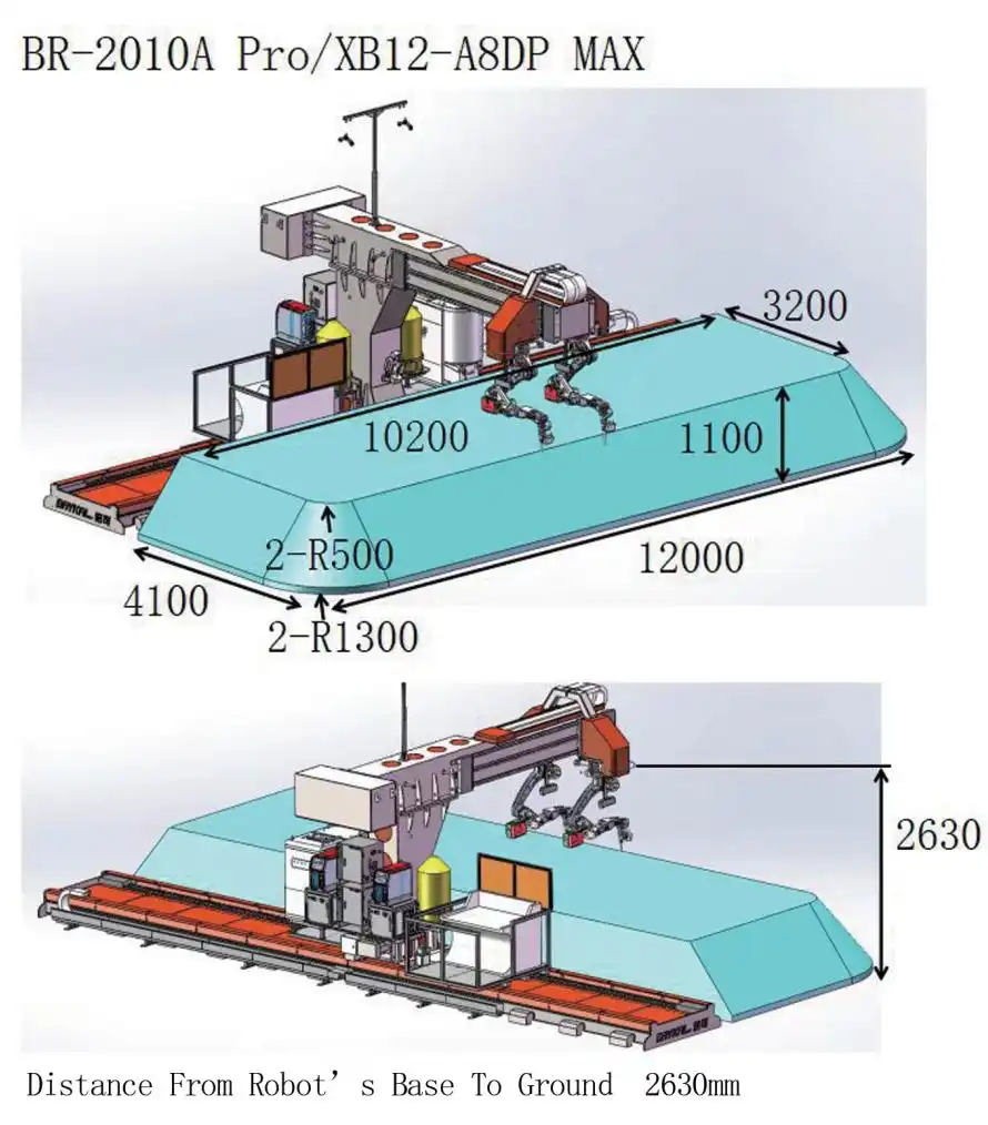
5) Equipment Installation Site: The concrete floor depth must be at least 200mm.